
Service Manual
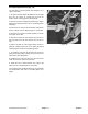


Installing the PTO Drive Shaft (Fig. 18, 19)
DANGER
Do not start the engine and engage the P.T.O.
lever when the P.T.O. shaft is not connected
to the gearbox on the cutting unit. If the en-
gine is started and the P.T.O. shaft Is allowed
to rotate, serious Injury could result.
The P.T.O. Drive Shaft has two major components.
When replacing it on the machine, the spline shaft
portion attaches to the traction unit and the tube portion
attaches to the cutting unit gearbox.
IMPORTANT: The P.T.O. shaft yokes must be exactly
in line with each other when the outer P.T.O. sleeve
is installed on the splined shaft. Remove the sleeve
and change the yoke position if alignment is not
correct. Misalignment of the yokes will shorten the
life of the P.T.O. Drive Shaft assembly and cause
Figure 18
unnecessary vibration when the cutting unit is op-
era
ted.
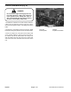
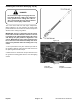
1. Line up the holes in the yoke and the input shaft of
the gearbox. Slide the yoke onto the shaft and secure
the parts together with the roll pin.
2. Mount the P.T.O. shield over the input shaft and onto
th
e gearbox mounting plate with the two self-tapping
screws.
Figure 19
1. PTO yoke 3. Roll pin
2. Yokes in phase 4. Capsc
rews & locknuts
Repairs Page 9 - 14 Groundsmaster
®
300 Series