
Service Manual
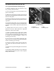


Seat Switch Replacement (Fig. 28, 29)
Lever Type Switch (S/N Below 30001) (Fig. 28)
1. Remove instrument cover and disconnect nega-
tive
(–) battery cable from battery.
2. Pivot seat forward and secure with support rod to
prevent it from falling.
3. (4WD units only) Remove (4) flange screws and (2)
locknuts securing sealing plate to frame above fuel tank.
Remove sealing plate.
4. Disconnect electrical connectors for seat switch. Re-
move
capscrew and locknut securing switch to mount-
ing bracket.
5. To install new seat switch, set it on mounting bracket
and make su
re locating pin on bottom of switch fits hole
in bracket. Secure switch in place with capscrew and
locknut.
6. Carefully lower seat, but do not sit on, or apply
pres
sure to the seat. There should be a slight gap
between the switch and seat plate.
7. Connect a continuity tester or ohm meter to switch
c
onnector. With seat in down position and no one on
seat, the switch circuit should have no continuity. If there
is continuity, check switch installation. If there is no
continuity, go to next step.
8. Set on the seat. The seat switch should have conti-
nuity
. If there is no continuity, check switch installation.
If there is continuity, go to next step.
9. Liberally coat inside of wiring connectors with skin-
o
ver grease and push wire harness connectors to-
gether.
10. (4WD units only) Install sealing plate to frame above
fu
el tank.
11. Disengage support rod lower the seat. Install lynch
pin through rod to hold seat in place. Connect negative
battery cable to battery.
Figure 28
(S/N Below 30001)
1. Connectors 3. Switch
2. Capscrew & locknut 4. Mounting bracket
Groundsmaster
®
300 Series Page 6 - 35 Repairs