
Operator's Manual


22
Operation
Note: Determine the left and right sides of the machine
from the normal operating position.
Controls
Traction Pedal
The traction pedal (Fig. 16) has two functions; one is to
make the machine move forward, the other is to make it
move backward. Using the heel and toe of the right foot,
depress top of pedal to move forward and bottom of pedal
to move backward. Ground speed is proportionate to how
far pedal is depressed. For maximum ground speed with no
load, traction pedal must be fully depressed while throttle is
in FAST position. Maximum speed forward is
approximately 9.5 mph (15 km/h). To get maximum power
under heavy load or when ascending a hill, have throttle in
FAST position while depressing traction pedal slightly to
keep engine rpm high. When engine rpm begins to
decrease, release traction pedal slightly to allow engine rpm
to increase.
When foot is removed from the traction pedal,
machine should stop; it must not creep in either
direction. If machine does creep, do not operate
until neutral assembly has been repaired and
adjusted; refer to Adjusting Traction Drive for
Neutral.
Caution
Turn Pedals
The left and right turn pedals (Fig. 16) are connected to the
left and right front wheel brakes since both brakes work
independently of each other. The brakes can be used to turn
sharply or to increase traction if one wheel tends to slip
while operating on a hillside. However, wet grass or soft
turf could be damaged when brakes are used to turn.
Tilt Steering Control
The tilt steering control is a lever on right side of steering
column (Fig. 16). Pull lever rearward to adjust steering
wheel to desired fore or aft operating position and push
lever forward to lock adjustment.
Do not leave lever in unlocked position.
Caution
Brake Pedal
Whenever the engine is shut off, the parking brake (Fig. 16)
must be engaged to prevent accidental movement of the
machine.
The hydrostatic transmission will not, at any time, act as a
parking brake for the machine. To engage parking brake,
push down fully on brake pedal and pull parking brake
knob out; then release the pedal. To release parking brake,
depress brake pedal until parking brake knob retracts. To
stop quickly, remove right foot from traction pedal and
depress the brake pedal. To permit straight stops, brake
cables must be evenly adjusted.
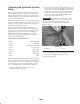
1
54
2
3
Figure 16
1. Traction pedal
2. Turn pedals
3. Brake pedal
4. Parking brake knob
5. Tilt steering control
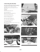
Lift Lever
The hydraulic lift lever (Fig. 17) has three positions:
FLOAT, TRANSPORT, and RAISE. To lower implement to
the ground, move lift lever forward into detent, which is the
FLOAT position. The FLOAT position is used for operation
and also when machine is not in operation. To raise
implement, pull lift lever backward to the RAISE position.
After implement is raised, allow lift lever to move to the
TRANSPORT position. Normally, implement should be
raised when driving from one work area to another, except
when descending steep slopes.
The exposed, rotating blades of the cutting unit or
other implements are hazardous.
Never raise a cutting unit or implement while the
blades or other components are rotating.
Caution