
Service Manual


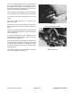


12. Insert the piston and connecting rod assembly into
the cylinder block using a ring compressor and a
wooden block. After insertion into the cylinder, properly
install the connecting rod bearings and rod caps and
tighten the bolts to the specified torque.
NOTE: The bearing assembly grooves in the connecting
ro
d cap should be on the same side when assembled.
13. Install the front plate. Remember to use a new
gasket.
14. Turn the crankshaft until the No. 1 piston is a top
dead center (TDC).
15. Drive the key into the crankshaft and install the
crankshaft gear onto the shaft if it has been disassem-
bled.
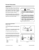
16. With the idler gear mating mark “1" properly aligned
wit
h the crankshaft mating mark ”1",install the idler gear
on to the idler shaft.
17. Insert the camshaft and gear assembly into the
c
ylinder block and align the idler gear mark “2" with the
camshaft gear mating mark ”2".
18. Install the injection pump camshaft assembly into
the
cylinder block and align the idler gear mating mark
“3" with the pump gear mark ”3". Remember to install
the bolt and washer which retain the injection pump
camshaft bearing.
19. Install the governor weight assembly and sliding
s
haft to the injection pump cam gear.
Figure 85
Installing piston and rod assembly
Figure 86
Mating marks of gears
Groundsmaster
®
300 Series Page 4 - 63 Cylinder Block Overhaul