
Service Manual


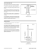


Injection Pump Disassembly (Fig. 47)
The injection pump may be disassembled to replace
wo
rn, damaged or defective components according to
the following procedures:
IMPORTANT: Clean external engine area near injec-
ti
on pump before disassembly. Do not spray water
on a hot injection pump. Do not remove Inter-cylin-
der adjusting plates unless necessary. If necessary,
scribe plates and housing carefully to ensure exact
repositioning upon reinstallation. Do not mix deliv-
ery valves, delivery valve seats, plungers or plunger
barrels from one cylinder to another. Handle these
parts carefully. Place these parts in clean diesel fuel
to prevent rust.
1. Remove the fuel pipes from the injection pump to the
in
jector nozzles.
2. Remove the fuel return hose by disconnecting the
c
ollar from the pump, or by removing the hose clamp.
3. Remove the tie rod cover. Disconnect the Tie Rod
retaining spring and Tie Rod from the Control Rack.
4. Remove the four injection pump mounting bolts.
5. Remove the injection pump from the cylinder block.
Make
note of the number and thickness of the adjusting
shims under the pump. The shims determine the injec-
tion timing.
6. Straighten the locking tabs on the plate which retains
the
Tappet Guide Pin). Rotate the pin 180", push in on
the Tappet slightly and remove the Guide Pin and Tap-
pet.
7. Remove the Lower Seat, Plunger Spring, Upper Seat,
C
ontrol Pinion and Plunger.
8. Remove the Delivery Valve Holder, Gasket, 0-ring,
V
alve Spring and Delivery Valve. Push the barrel as-
sembly out from below.
9. Remove the components of the other two injector
pumps usin
g the same procedure.
10. To remove the Control Rod, remove the E-rings,
Ungleich set spring, and Ungleich set plate. Slide the
rack from the pump body.
11. To remove the smoke set plate, remove the cotter
pin,
washer and return spring.
Figure 47
1. E-ring 15. O-ring
2. Ungleich set spring 16. Delivery valve holder
3. Ungleich set plate 17. Bolt/washer
4. Pump housing 18.
Adjusting plate
5. E-ring 19.
Tappet guide pin
6. Return spring 20.
Plate
7. Smoke set plate 21.
Control rack
8. Air breather screw 22. Plunger control sleeve
9. Washer 23.
Upper spring seat
10. Hollow screw 24.
Pump plunger spring
11. Pump element ass’y 25. Lower spring seat
12. Delivery valve ass’y 26. Shim plate
13. Gasket 27.
Tappet
14. Delivery valve spring
Groundsmaster
®
300 Series Page 4 - 41 Fuel System Service