
Service Manual
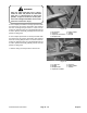


8. Line up holes in yoke and input shaft of gear box.
Slide yoke onto shaft and secure parts together with roll
pin (3/16 x 1-1/2 in.). Tighten (2) capscrews and
locknuts securing yoke to input shaft.
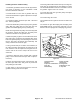
9. Mount PTO shield over input shaft and onto gear box
mount
ing plate with two self-tapping screws.
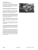
10. Attach lift chains to lift arm and cutting unit with six
(6) shackles, shackle pins (3/8 x 1-1/2 in.) and cotter
p
ins (1/8 x 3/4 in.). Adjust chain length so both become
tight at the same time when lifting lift arm.
11. Connect ends of tension spring between fourth link
of
rear chain and eye of cotter pin that holds cylinder pin
in place. Adjust length of chain so rear caster wheels
are off the ground in transport position.
Figure 20
1. PTO yoke 3. Roll pin
2. Yokes in phase 4. Capsc
rews & locknuts
Figure 21
1. PTO shield 4. Spring in 4th link
2. Self-tapping screws 5. Spring in cotter pin
3. Lift chain
Groundsmaster
®
300 Series Page 11 - 17 Repairs