
Service Manual


Installation
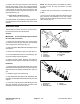
1. Coat new shaft seals with grease and install in axle
case and bevel gear case as shown (Fig. 8).
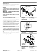
2. Install the lower bevel gear, and bevel gear shaft in
t
he axle case cover. Coat a new O-ring with grease and
install the axle case cover (Fig. 9). Tighten cover screws
to 17 to 20 ft-lbs. (23 to 27 Nm).
3. Slide the bevel gear case over the bevel gear shaft
and install the thrust
washer, spacer, bevel gear, and
collar. Make sure the bevel gear shaft is completely
seated in the upper and lower bearings (Fig. 9).
4. Install the knuckle pin. Use medium strength Loctite
thread locker and tighten the
knuckle pin mounting
screws to 17 to 20 ft-lbs. (23 to 27 Nm).
2
1
3
Figure 8
1. Axle case 3. Shaft seal
2. Bevel gear case
17 to 20 ft–lbs.
(23 to 27 Nm)
Thread Locker
10
8
7
6
5
2
17 to 20 ft–lbs.
(23 to 27 Nm)
4
1
9
Figure 9
1. Axle case cover 6. Spacer
2. Lower bevel gear 7.
Upper bevel gear
3. Bevel gear shaft 8. Collar
4. Lower bearing 9. Upper
bearing
5. Thrust washer 10. Knuckle
pin
4WD Rear Axle (Rev. G) Page 10.1 – 8 Groundsmaster 328–D
(Dae Dong Axle)
3