
Service Manual


Bevel Gear Case and Axle Case
The following procedures assume the rear axle assem-
bly has been removed from the machine.
35 to 41 ft–lbs.
(47 to 56 Nm)
1
6
Removal
5
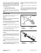
ers. Remove the bevel gear case/axle case assembly
and O-ring from the axle support (Fig. 3).
1. Remove the mounting screws, nuts, and lock wash-
4
2
2. Mark both right and left bevel gear case/axle case
3
assemblies.
35 to 41 ft–lbs.
IMPORTANT: Do not interchange right and left
(47 to 56 Nm)
bevel gear case/axle case assemblies.
Figure 3
1. Cap screw 5. Bevel gear case/axle
2. Lock nut case assembly
3. Lock washer 6. O-ring
4. Axle support
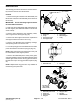
3. Remove the axle cover mounting screws. Remove
the axle cover from the axle case as an assembly
(Fig. 4).
1
2
3
4
Figure 4
1. Axle case 3. Mounting screw
2. Axle cover assembly 4. O-ring
4. Remove the axle case support mounting screws, the
axle case support, and the support shims (Fig. 5).
2
1
3
4
Figure 5
1. Axle case 3. Mounting screw
2. Axle case support 4. Support
shim
4WD Rear Axle (Rev. G) Page 10.1 – 6 Groundsmaster 328–D
(Dae Dong Axle)