
Service Manual


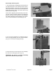


30. Remove the commutator ring (Fig. 47). Inspect for
cracks, burrs and scoring.
IMPORTANT: Handle the commutator ring with care,
as
it is easily broken.
31. Remove the commutator from the rotor (Fig. 48).
IMPORTANT: To prevent damage, DO NOT use a
screwdriver
to remove the commutator. Use a wood
dowel if necessary.
32. The commutator is made up of two round plates,
pi
nned and bonded together as a permanent assembly
that cannot be disassembled. Inspect the ground sur-
faces of the commutator. The holes and edges should
be free of nicks. The ground surfaces should be free of
scoring. The edges should be sharp.
NOTE: The commutator and commutator ring are a
matched set. If either is
worn or damaged, the set must
be replaced.
IMPORTANT: Five alignment pins connect the com-
m
utator to the rotor with a slip fit. Care and minimum
force should be used to separate the two compo-
nents.
33. Remove the five alignment pins (Fig. 49).
Figure 47
Figure 48
Figure 49
®
Repairs P
age 8 - 30 Groundsmaster 300 Series