
Service Manual


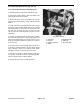


Traction (Neutral) Switch Replacement (Fig. 25)
1. Remove the two wires that are connected to the
traction switch.
2. Loosen two (2) screws and remove the switch.
3. Install new switch. DO NOT over-tighten screws as
th
e switch case could break.
NOTE: Apply “Loctite 271” or equivalent to threads of
switch screws before installing.
4. Reconnect the two wires to the new switch. Make sure
that one wire is connected to the “COMMON” terminal,
and one wire is connected to the “NORMALLY OPEN”
(N.O.) terminal.
IMPORTANT: The traction switch has three (3) ter-
m
inals. If the two (2) wires are not connected to the
Figure 25
“COMMON” and “NORMALLY OPEN” (N.O.) termi-
nals, t
he engine will be unable to start and the safety
interlock circuit will not function properly.
TRACTION
NEUTRAL SWITCH
If the wires are not correctly installed to the
switch, the engine could start with the trac-
tion pedal in forward or reverse.
CAUTION
5. Coat the switch terminals and wires with skin-over
grease.
6. Check traction control neutral adjustment. (See Trac-
tion Control Neutral Adjustment in the Adjustments sec-
tion of Chapter 4 - HYDRAULIC SYSTEM.
7. Actuate the pump lever to insure all parts are operat-
ing fr
eely and seated properly.
8. Loosen jam nut. Rotate switch adjusting screw until
there is a gap between head of screw and switch button.
9. Rotate adjusting screw until it contacts the switch
button. Continue to rotate the screw until the circuit is
completed (switch “clicks”). After the switch clicks, ro-
tate the adjusting screw an additional 1/2 turn. Tighten
jam nut.
Repairs P
age 6 - 32 Groundsmaster
®
300 Series