
Operator's Manual
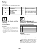


Figure12
1.Latchpin
3.Spacer,1/2inch(13mm)
2.Spacer,3/16inch(5mm)
2.Removethelatchpin,slidethecasterfromthe
support,andchangethespacers(Figure12).
3.Installthecasterinthesupportandinsertthelatch
pin(Figure12).
AdjustingtheHandleHeight
Thehandlepositioncanbeadjustedtomatchthe
operator’sheightpreference.
1.Removethehairpincotterpinsandclevispinsfrom
thedriveleversandneutrallocks(Figure13).
Figure13
1.Controlrod
5.Neutrallock
2.Clevispin
6.Hairpincotterpin
3.OperatorPresence
Controllever(OPC)
7.Lefthandleshown
4.Handle8.Drivelever
2.Loosentheupperbolts(3/8x1-1/4inches)and
angenutsecuringhandletorearframe(Figure14).
3.Removethelowerbolts(3/8x1inch)andange
nutssecuringhandletorearframe(Figure14).
4.Pivotthehandletothedesiredoperatingposition
andinstallthelowerangebolts(3/8x1inch)and
angenutsintothemountingholes.Tightenall
angebolts.
Figure14
1.Upperhandle6.Lowermountingholes
2.Rearframe
7.Lowposition
3.Flangebolt(3/8x1inch)
8.Middleposition
4.Locknut(3/8inch)
9.Highposition
5.Uppermountinghole
5.Adjustthecontrolrodlengthbyrotatingthecontrol
rodintherodtting(Figure13).
6.Installahairpincotterbetweenthedriveleversand
neutrallocksandintotheclevispins(Figure13).
Note:Makesuretheclevispinsareinsertedinto
theneutrallocks.
7.Checktheparkingbrakeadjustment.Referto
CheckingtheBrakesinBrakeMaintenance,
page31.
20