
Operator's Manual


6.Ifthereisnoadjustmentleftintheturnbuckleand
thebeltisstillloose,therearidlerpulleyneedstobe
positionedtothemiddleorfronthole(Figure48).
Usetheholethatwillgivethecorrectadjustment.
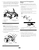
7.Whentheidlerpulleyismovedthebeltguidemust
bemoved.Movethebeltguidetothefrontposition
(
Figure48).
g017651
Figure48
1.Rearidlerpulley4.Beltguideinbackposition
2.Rearhole5.Frontidlerpulley
3.Fronthole
8.Checkthebeltguideundertheengineframefor
properadjustment(Figure49).
Note:Thedistancebetweenthebeltguideand
themowerbeltshouldbe3/4inch(19mm)when
youengagethemowerbelt(
Figure49).Adjustthe
mowerbeltasnecessary.Thedisengagedbeltshould
notdragorfalloffthepulleywhentheguidesand
belttensionareproperlyadjusted.
9.Checkthebladebrakeadjustment;refertoAdjusting
theBladeBrake.
Figure49
1.Beltguide
AdjustingthePTOEngagement
Linkage
ThePTOengagementlinkageadjustmentislocated
beneaththefrontlefthandcorneroftheenginedeck.
1.Disengagethebladecontrol(PTO)leverandsetthe
parkingbrakes.
2.Stoptheengineandwaitforallmovingpartstostop
beforeleavingtheoperatingposition.
3.Engagethebladecontrollever(PTO).
4.Checktheclearancebetweenthebellcrankandthe
transmissionoutputshaft(
Figure50).
Note:Theclearanceshouldbe1/16-1/8inch(2-3
mm).
g017648
1
2
3
4
Figure50
1.1/16-1/8inch(2-3mm)3.Transmissionoutputshaft
2.Bellcrank
4.Clevis
5.Makesuretheassistarmisagainsttherearassistarm
stoponthedeck(Figure51).
6.Disengagethebladecontrol(PTO)lever.
7.Theassistarmshouldcontactthefrontassistarm
stoponthedeck.Ifitdoesnotcontact,adjustthe
bellcranksoitisclosertothetransmissionoutput
shaft(
Figure50andFigure51).
36