
Service Manual


Removal(Figure356)(continued)
2
3
7
8
6
5
4
1
1
FRONT
g277167
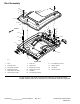
Figure357
1.Condensationdrainhose(2used)5.A/Chose:compressortocondenser
2.Heatervalve
6.A/Chose:condensertodrier
3.A/Chose:evaporatortocompressor
7.Heaterhose:thermostattoheatervalve
4.Heaterhose:heatervalvetoheatercore8.Heaterhose:heatercoretowaterpump
4.ReadtheGeneralPrecautionsforRemovingandInstallingtheAir
ConditioningSystemComponents(page10–3).
CAUTION
Theairconditioningsystemisunderhighpressure.Donotloosen
anysystemttingorcomponentuntilafterthesystemhasbeen
completelydischargedbyacertiedA/Cservicetechnician.
5.HaverefrigerantevacuatedfromairconditioningsystembyacertiedA/C
servicetechnician.
6.Labelandremovehosesfromheatercore,evaporatoranddrier−receiver.
Immediatelycaphosesandttingstopreventmoistureandcontaminants
fromenteringthesystem.
7.Loosenhoseclampthatsecuresairducthosetoheater/evaporatorassembly
covers.Slidehosefromcovers.
8.Removescrewsthatsecuretopcovertobottomcover.Removetopcoverto
accessheater/evaporatorassembly.
9.Disassembleheater/evaporatorassemblyusingFigure356asaguide.
10.Ifnecessary,removefanresistorfromblowerfanassembly(Figure358).
Note:Thereplacementofthedrier−receiverisrecommendedwheneverthe
airconditioningsystemisopened.
OperatorCab
(Formodels30603and30607)
:ServiceandRepairs
Page10–14
Groundsmaster
®
4000-D&4010-D
13202SLRevF