
Service Manual


Disassembly(Figure312)(continued)
3.Atfrontofcontrolarm,removescrew(item29)andlocknut(item5)that
securecontrolarmcoverstoeachother.
4.Removeve(5)washerheadscrews(item3)thatsecureeachcoverto
controlarmpanel.
5.Removecontrolarmcoversfrommachine.AsLHcover(item4)isremoved
fromcontrolarm,unplugwireharnessconnectorfromheadlightswitchif
equipped.
6.RemoveelectricalcomponentsfromcontrolarmasneededusingFigure
312asaguide.
7.Ifnecessary,removecontrolarmpanelandsupportsfrommachineusing
Figure312andFigure313asguides.
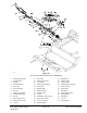
Assembly(Figure313)
2
3
6
7
5
4
1
8
9
10
11
5
11
12
1
g276873
Figure313
1.Flatwasher
7.Screw
2.Seatbeltbuckle
8.Armsupport
3.Couplingnut
9.Hexnut
4.Spacer10.Supportbracket
5.Carriagescrew(5used)11.Flangenut(5used)
6.Capscrew12.Supportchannel
1.InstallallremovedelectricalandcontrolarmcomponentsusingFigure312
andFigure313asguides.
2.Positioncoverstocontrolarm.AsLHcover(item4)isplaced,plugwire
harnessconnectortoheadlightswitchifequipped.
3.Secureeachcovertocontrolarmwithve(5)washerheadscrews(item
3).Installscrew(item29)andlocknut(item5)tosecurecoversatfrontof
controlarm.
4.Positioncoverplateandspacerstooutsideofcontrolarm.Securewithtwo
(2)angeheadscrews.
Groundsmaster
®
4000-D&4010-D
Page8–23
Chassis:ServiceandRepairs
13202SLRevF