
Service Manual


ServiceBrakeSwitches
13 to 17 in−lb
(1.5 to 1.9 N−m)
1
3
5
2
4
6
7
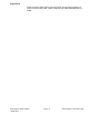
g276006
Figure197
1.Flangescrew(3used)5.Screw(2perswitch)
2.Cover6.Switchnut(2used)
3.Switchbracket
7.Clip(3used)
4.Brakeswitch(2used)
Thetwo(2)switchesusedfortheservicebrakesarenormallyopenswitchesthat
arelocatedunderthefootrestpanel(Figure197).Theservicebrakeswitches
provideinputsfortheTECcontroller.Whenabrakepedalisnotdepressed,the
brakepedalassemblycontactstheswitchplungertoclosetheswitch.Whena
brakeisapplied,thebrakepedalassemblymovesawayfromtheswitchplunger,
allowingtheswitchplungertoextendandtheswitchtoopen.
Testing
1.Beforedisconnectingaservicebrakeswitchfortesting,theswitchandits
circuitwiringshouldbetestedasaTECinputwiththeInfoCenterDisplay
(seeInfoCenterDisplay(page6–6)).IftheInfoCenterveriesthatthebrake
switchandcircuitwiringarefunctioningcorrectly,nofurtherswitchtestingis
necessary.If,however,theInfoCenterdeterminesthatthebrakeswitchand
circuitwiringarenotfunctioningcorrectly,proceedwithtest.
2.MakesureignitionswitchisOFF .Removekeyfromignitionswitch.
3.Removebrakecoverandswitchplateonoperatorplatformtoaccessservice
brakeswitches(Figure197).
4.Disconnectswitchelectricalconnectorfromthemachinewireharness.
5.Checkthecontinuityoftheswitchbyconnectingamultimeter(ohmssetting)
acrosstheconnectorterminals.
6.Whentheservicebrakeswitchplungerisdepressed,thereshouldbe
continuity(zeroresistance)betweentheswitchterminals.
7.Whentheservicebrakeswitchplungerisextended,thereshouldbeno
continuity(inniteresistance)betweentheswitchterminals.
8.Replaceservicebrakeswitchifnecessary.
9.Connectswitchelectricalconnectortothemachinewireharnessaftertesting.
Securebrakecoverandswitchplatetooperatorplatform.
ElectricalSystem:ComponentTesting
Page6–42
Groundsmaster
®
4000-D&4010-D
13202SLRevF