
Service Manual


Removal(Figure322)(continued)
2
3
1
4
(18 ft−lb)
25 N·m
g276884
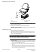
Figure324
1.Seat3.Screw(M8x12)(3used)
2.Suspensionassembly4.Screw(M8x16)
8.Removefour(4)torxheadscrewsthatsecureseattoseatsuspension
(Figure324).Notethatthescrewneartheseatadjustmenthandleislonger
thantheotherthree(3)screws.
9.Liftseatfromseatsuspensionandremovefrommachine.
Note:RefertoOperatorSeatSuspension(page8–38)inthissectionifseat
suspensionserviceisnecessary.
Installation(Figure322)
1.Carefullypositionseattoseatsuspension.
2.Secureseattoseatsuspensionwithfour(4)torxheadscrews(Figure324).
Makesurethatlongerscrewispositionedneartheseatadjustmenthandle.
Torquescrews25N·m(18ft−lb).
IMPORTANT
Makesuretonotdamagetheelectricalharness,controlcableor
otherpartswhilemovingthecontrolarmassembly.
3.Positionandsecurecontrolarmassemblytoseat.Installallfastenersbefore
fullytighteningthem.
A.Securesupportbracket(item3)andsupportchannel(item2)withange
nut(item4)andcarriagescrew(item1).
B.Securecontrolarmsupport(item7)tocouplernut(item9)withscrew
(item8).
C.Placeatwasher(item6),seatbeltlatch(item21)andspacer(item10)
betweenseatandcontrolarmsupport(item7).Securewithcapscrew
(item5)andsecondatwasher(item6).
Chassis:ServiceandRepairs
Page8–34
Groundsmaster
®
4000-D&4010-D
13202SLRevE