
Service Manual


FlasherSwitch(Groundsmaster4010−D)
1
2
g276015
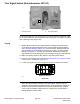
Figure206
1.Steeringcolumn
2.Flasherswitch
OnGroundsmaster4010−Dmachines,theasherswitchisusedasaninputfor
theTECcontrollertoprovidepowerforthefourwayashers.Theswitchis
locatedonthesteeringtower(Figure206).
Testing
1.Beforedisconnectingtheasherswitchfortesting,theswitchanditscircuit
wiringshouldbetestedasaTECinputwiththeInfoCenterDisplay(see
InfoCenterDisplay(page6–6)).IftheInfoCenterveriesthattheasher
switchandcircuitwiringarefunctioningcorrectly,nofurtherswitchtestingis
necessary.If,however,theInfoCenterdeterminesthattheasherswitchand
circuitwiringarenotfunctioningcorrectly,proceedwithtest.
2.MakesureignitionswitchisOFF .Removekeyfromignitionswitch.
3.Removefrontsteeringtowercover(seeSteeringT ower(Formachinesserial
numberbelow:400000000)(page8–3)).
4.Locateasherswitchandunplugwireharnessconnectorfromswitch.
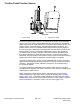
BACK OF SWITCH
g276016
Figure207
5.TheswitchterminalsaremarkedasshowninFigure207.Thecircuit
logicoftheasherswitchisshowninthechartbelow.Withtheuseofa
multimeter(ohmssetting),theswitchfunctionsmaybetestedtodetermine
whethercontinuityexistsbetweenthevariousterminalsforeachposition.
Verifycontinuitybetweenswitchterminals.Replaceasherswitchiftesting
identiesafaultyswitch.
ElectricalSystem:ComponentTesting
Page6–52
Groundsmaster
®
4000-D&4010-D
13202SLRevE