
Service Manual


Installation(Figure94andFigure95)
1.Ifttingswereremovedfromgearpump,lubricateandplacenewO−rings
ontottings.Installttingsintopumpopeningsusingmarksmadeduringthe
removalprocesstoproperlyorientatettings.Tightenttings(seeInstalling
theHydraulicFittings(SAEStraightThreadO-RingFittings)(page5–10)).
2.MakesuremountingandO−ringsealingsurfacesonthegearpumpand
pistonpumpareclean.
3.ApplycleanhydraulicoiltogearpumpangeO−ring(item11).PlaceO−ring
onthegearpump.
IMPORTANT
Positiongearpumptothepiston(traction)pumpsothatthegear
pumpinlet(suction)portsarefacingdown.
IMPORTANT
Acasedrainexistsinthepiston(traction)pumpandasuctionport
isneartheinputshaftofthegearpump(Figure96).Beforethegear
pumpisinstalledtothepistonpump,makesurethatplugsplacedin
eitheroftheseportsareremoved.Failuretoremoveplugswillcause
excessivepressureinthepistonpumpanddamageseals.Also,
beforesecuringgearpumptopistonpump,llpistonpumphousing
withcleanhydraulicoilthroughcasedrainhole.
4.Removeplugsthatwereplacedinpistonpumpcasedrainandgearpump
suctionport.Fillpistonpumphousingwithcleanhydraulicoilthroughcase
drainhole.
5.Positiongearpumptothepiston(traction)pumpsothatthepumpinletports
arefacingdown.
6.Aligngearteethandslidegearpumpinputshaftintopistonpumpshaft.
Securegearpumptopistonpumpwithtwo(2)capscrewsandatwashers.
7.Removecapsandplugsfromhydrauliclinesandttings.Usinglabelsplaced
duringgearpumpremoval,properlyinstalllinestogearpump(seeInstalling
HydraulicHosesandTubes(O-RingFaceSeal)(page5–8)).
2
3
1
g275423
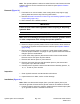
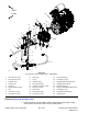
Figure97
1.Piston(traction)pump
3.Pistonpumpcasedrain
2.Gearpump
HydraulicSystem:ServiceandRepairs
Page5–100
Groundsmaster
®
4000-D&4010-D
13202SLRevE