
Service Manual


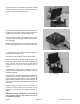


11. Remove the valve ring (Fig. 32). Remove and dis-
card the two seal rings (Fig. 33). The valve ring should
be free of nicks and scoring.
Figure 32
Figure 33
12. Remove the valve plate by lifting it from the isolation
manifold (Fig. 34).
13. Inspect the slot edges and ground surfaces. If the
valve
plate shows nicks or scoring or the edges are not
sharp, it must be replaced.
NOTE: The valve ring and valve plate are a matched set
an
d must be replaced as a set.
Figure 34
Groundsmaster
®
300 Series Page 8 - 25 Repairs