
Service Manual


7. Remove the cap screws, locknuts, carriage bolts, lock
washers and nuts holding the brake mount and pedal
assembly in place. Lay the brake mount and the pedal
assembly on the wheel.
8. Have a helper push down slightly on the left push arm
wh
ile you remove the block of wood between the push
arm and the chassis. Slowly and carefully allow the push
arm to move upward until all spring load is released.
9. Remove the cap screws, locknuts, support plate and
push arm br
acket holding the left side of the push arm
and pivot shaft to the main frame.
10. Remove the cap screws, locknuts, reinforcement
a
nd push arm bracket holding the right side of the push
arm and pivot shaft to the main frame. The entire push
arm and pivot shaft assembly should now be free of the
main frame.
11. Drive the roll pins out of the pivot shaft and slide the
pus
h arm assemblies off of the shaft.
12. Drive the pushing out of both push arm pivot tubes.
Clean the inside of the pivot tubes to remove all dirt and
other material.
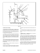
Figure 25
Figure 26
Figure 27
Groundsmaster
®
300 Series Page 11 - 19 Repairs