
Service Manual


TestProcedure(continued)
4.ReadallWarning,Cautions,andprecautionslistedatthebeginningofthis
section.
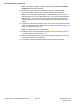
5.Cleanthejunctionofthehydraulichoseandupperttingonthefrontsideof
theliftcontrolmanifold(Figure46).
6.Disconnectthehydraulichosefromtheupperttingonthefrontsideofthe
liftcontrolmanifold(Figure46).Thishoseisfromthegearpumpoutletand
providesuidowtotheliftcontrolmanifold(Figure47).
7.InstallaT-connectorwitha34,500kPa(5,000psi)hydraulicpressuregauge
inserieswiththeliftcontrolmanifoldttinganddisconnectedhose.
8.Starttheengineandrunitatlow-idlespeed(1,400rpm).Checkfor
hydraulic-uidleaksfromthetestconnectionsandcorrectbeforecontinuing
thetest.
9.Withtheenginerunning,movethethrottletofullspeed(3,000rpm).
IMPORTANT
PresstheliftswitchtotheRAISEpositiononlyuntilyougetasystem
pressurereading.HoldingtheliftswitchintheRAISEpositionforan
extendedperiodmaydamagetheliftcontrolmanifold.
10.Monitorthepressuregaugecarefullywhileyoupresstheliftswitchtothe
RAISEposition.Thesystempressureshouldbeapproximately20,700kPa
(3,000psi)astheimplementreliefvalvelifts.
11.ReturntheliftswitchtotheNEUTRALposition,shutofftheengine,andrecord
thetestresults.
12.Ifspecicationisnotmet,repairorreplacetheimplementreliefvalveinthe
gearpump;refertoServicingtheGearPump(page4–109).Also,considera
leakingliftcylinder,damagedliftcontrolmanifold,orworngearpump.
Note:Theimplementreliefvalvepressurecanalsobetestedwitha
hydraulictester(pressureandow)inserieswiththegearpumpttingand
disconnectedhose.Usethepressuregaugesonthehydraulictesterand
followTestingtheImplementReliefPressure(UsingPressureGauge)(page
4–48).
13.Releasepressurefromthehydraulicsystem;refertoReleasingPressure
fromtheHydraulicSystem(page4–11).
14.DisconnecttheT-connectorwithtestgaugefromtheliftcontrolmanifold
ttingandhydraulichose,andconnectthehydraulichosetotheliftcontrol
manifoldttingagain.
HydraulicSystem:TestingtheHydraulicSystem
Page4–50
Groundsmaster7210
16222SLRevE