
Service Manual


Installation(Figure278)(continued)
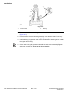
8.Useadepthgaugetomeasurethedistancefromtheendfaceoftheinput
shaft/piniongeartothematingsurfaceofthebearingcase.Subtractthe
“DesignConeCenterDistance”fromthisdistancetodetermineinitialshim
thickness(Figure280).
DESIGNCONECENTERDISTANCE(distancefrommatingsurfaceofaxle
supporttoendfaceofpiniongear):47.5+0.05mm(1.870+0.002in).
Note:Bearingcaseshimsareavailablein0.1mm(0.004in)and0.2mm
(0.008in)thickness.
9.CoatnewO-ringswithgreaseandinstallthebearingcaseinthegearcase.
Placeshimsonthegearcaseandtemporarilyinstallgearcaseassembly
intoaxlecase.Tightenmountingnutsandscrewsfrom47to56N·m(35
to41ft-lb).
1
2
3
4
g276528
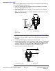
Figure281
1.Axlecase3.Dialindicator
2.Screwdriver4.Inputshaft/piniongear
10.Insertascrewdriverthroughthedrainplugholetoholdringgearand
measurethepiniongeartoringgearbacklash(Figure281).
PINIONGEARTORINGGEARBACKLASH:0.10to0.40mm(0.004to
0.016in)
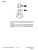
11.Adjustbacklashbyincreasingorreducinggearcaseshimthickness.
12.Checkpiniongeartoringgearengagement(seePinionGeartoRingGear
Engagement(page7–48)).
13.Placethecorrectcombinationofshimsonthegearcase.Tightenmounting
nutsandscrewsfrom47to56N·m(35to41ft-lb).
14.Installretainingringsanddrivengearoninputshaft/piniongear.
15.Ifthedrivegear(ondrivemotorshaft)wasremoved,installtheretainingrings
anddrivegearonthemotorshaft.
16.Useanewgasketandinstallthecoverplate.UseanewO-ringandinstall
thedrivemotor.
Groundsmaster
®
4100-D&4110-D
Page7–41
Axles,PlanetariesandBrakes:ServiceandRepairs
13203SLRevF