
Service Manual


KeySwitch
REAR VIEW
FRONT VIEW
START
STOP
RUN
3
2
4
5
6
1
g275990
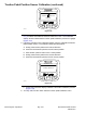
Figure180
Thekeyswitchislocatedonthecontrolpanelandhasthree(3)positions:STOP ,
RUNandSTART(Figure180).TheToroElectronicController(TEC)monitors
theoperationofthekeyswitch.
Testing
1.Parkmachineonalevelsurface,lowercuttingdecks,engageparkingbrake
andstopengine.Removekeyfromkeyswitch.
2.Beforedisconnectingthekeyswitchfortesting,theswitchanditscircuit
wiringshouldbetestedasaTECelectricalinputusingtheInfoCenterDisplay
(seeInfoCenterDisplay(page6–7)).Ifinputtestingveriesthatthekey
switchandcircuitwiringarefunctioningcorrectly,nofurtherkeyswitchtesting
isnecessary.If,however,inputtestingdeterminesthatthekeyswitchand
circuitwiringarenotfunctioningcorrectly,proceedwiththefollowingkey
switchtestingprocedure.
3.Removecontrolarmcoverstogainaccesstokeyswitch(seeControlArm
(page8–12)).
4.MakesurethekeyswitchisintheOFFposition.Disconnectwireharness
connectorfromkeyswitch.
5.ThekeyswitchterminalsareidentiedinFigure180andthecircuitryofthe
switchisshowninbelowchart.Withtheuseofamultimeter(ohmssetting),
theswitchfunctionscanbetestedtodeterminewhethercontinuityexists
betweenthevariousterminalsforeachswitchposition.Verifycontinuity
betweenswitchterminals.
SWITCHPOSITIONCIRCUITS
STOP
1+6
RUN1+3+4+5+6
START
1+2+4+5+6
Note:Thekeyswitchterminals1and6areconnectedinternally.Terminals4
and5arealsoconnectedinternally.Theseterminalsshouldhavecontinuity
regardlessofswitchposition.
6.Replacekeyswitchiftestingdeterminesthatitisfaulty.
7.Ifthekeyswitchtestscorrectlyandacircuitproblemstillexists,checkwire
harness(seeAppendixA(pageA–1)).
8.Aftertestingiscomplete,connectmachinewireharnessconnectortokey
switch.Securecontrolarmcoverstomachinewithremovedfasteners(see
ControlArm(page8–12)).
ElectricalSystem:ComponentTesting
Page6–28
Groundsmaster
®
4100-D&4110-D
13203SLRevF