
Service Manual


Removal(Figure147)
1.ReadtheGeneralPrecautionsforRemovingandInstallingHydraulicSystem
Components(page5–83).
2.Topreventcontaminationofhydraulicsystemduringmanifoldremoval,
thoroughlycleanexteriorofPTOmanifoldandttings.
3.Disconnectwireharnessconnectorfromtheproportionalreliefvalvecoil
onthePTOmanifold.
4.Disconnecthydrauliclinesfrommanifoldandputcapsorplugsonopen
hydrauliclinesandttings.Labeldisconnectedhydrauliclinesforproper
installation.
2
1
3
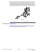
g275408
Figure148
1.RHPTOmanifold3.Flangescrew(2used)
2.Controllermount
5.RemovePTOmanifoldfromtheframeusingFigure147asaguide.
Note:TheangeheadscrewsthatsecuretherightsidePTOmanifoldalso
securesthecontrollermounttotheframe(Figure148).Supportcontroller
mountbeforeremovingtherightsidePTOmanifold.
6.Ifhydraulicttingsaretoberemovedfrommanifold,markttingorientationto
allowcorrectassembly.RemovettingsfrommanifoldanddiscardO−rings.
Groundsmaster
®
4100-D&4110-D
Page5–161
HydraulicSystem:ServiceandRepairs
13203SLRevF