
Service Manual


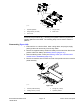


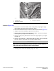


Table Of Contents
- Title Page
- Revision History
- Reader Comments
- NOTES
- Preface
- Table of Contents
- Chapter 1 : Safety
- Chapter 2 : Specifications and Maintenance
- Chapter 3 : Troubleshooting
- GEARS – The Systematic Approach to Defining, Diagnosing and Solving Problems
- General Hydraulic System Problems
- Traction Circuit Problems
- Mow Circuit Problems
- Lift Circuit Problems
- Steering Circuit Problems
- Engine Cooling Fan Circuit Problems
- Operator Advisories
- Fault Codes
- Starting Problems
- General Run and Transport Problems
- Cutting Deck Operating Problems
- Cutting Deck Lift/Lower Problems
- Aftercut Appearance
- Chapter 4 : Yanmar Diesel Engine
- Chapter 5 : Hydraulic System
- General Information
- Hydraulic Schematic
- Hydraulic Flow Diagrams
- Testing
- Precautions for Hydraulic Testing
- Which Hydraulic Tests Are Necessary?
- Traction Circuit Charge Pressure (Using Pressure Gauge)
- Traction Circuit Relief Pressure (Using Pressure Gauge)
- Counterbalance Pressure (Using Pressure Gauge)
- Reverse Traction Circuit Reducing Valve (PR) Pressure (Using Pressure Gauge)
- Rear Traction Circuit Relief Valve (RV) Pressure (Using Pressure Gauge)
- Piston (Traction) Pump Flow Test (Using Tester with Pressure Gauge and Flow Meter)
- Cutting Deck Circuit Pressure (Using Pressure Gauge)
- PTO Relief Pressure (Using Tester with Pressure Gauge and Flow Meter)
- Cutting Deck Motor Case Drain Leakage (Using Tester with Pressure Gauge and Flow Meter)
- Lift/Lower Circuit Relief Pressure (Using Pressure Gauge)
- Steering Circuit Relief Pressure (Using Pressure Gauge)
- Steering Cylinder Internal Leakage
- Engine Cooling Fan Circuit (Using Pressure Gauge and Phototac)
- Engine Cooling Fan Motor Case Drain Leakage Test
- Gear Pump Flow (Using Tester with Pressure Gauge and Flow Meter)
- Adjustments
- Service and Repairs
- General Precautions for Removing and Installing Hydraulic System Components
- Check Hydraulic Lines and Hoses
- Priming Hydraulic Pumps
- Flush Hydraulic System
- Filtering Closed−Loop Traction Circuit
- Charge Hydraulic System
- Hydraulic Reservoir
- Radiator and Oil Cooler Assembly
- Gear Pump
- Gear Pump Service
- Piston (Traction) Pump
- Piston (Traction) Pump Service (For machines serial number below: 400000000)
- Piston (Traction) Pump Service (For machines serial number above: 400000000)
- Rear Axle Motor
- Front Wheel Motors
- Rear Axle and Front Wheel Motor Service
- Rear Traction Manifold
- Rear Traction Manifold Service
- Combination Manifold
- Combination Manifold Service
- Steering Control Valve (For machines serial number below: 400000000)
- Steering Control Valve (For machines serial number above: 400000000)
- Steering Control Valve Service (For machines serial number below: 400000000)
- Steering Control Valve Service (For machines serial number above: 400000000)
- Steering Cylinder
- Steering Cylinder Service
- Engine Cooling Fan Motor
- Engine Cooling Fan Motor Service
- Cutting Deck Motors
- Cutting Deck Motor Service (Sauer−Danfoss)
- Cutting Deck Motor Service (Casappa)
- PTO Manifold
- PTO Manifold Service
- Center Deck Lift Cylinders
- Wing Deck Lift Cylinders
- Lift Cylinder Service
- Chapter 6 : Electrical System
- General Information
- Adjustments
- Electrical System Quick Checks
- Component Testing
- Key Switch
- Fuses
- Operator Cab Fuses (Groundsmaster 4110−D)
- Fusible Link Harness
- PTO Switch
- HI/LOW Speed, Engine Speed and Cutting Deck Lift Switches
- Cruise Control Switch
- Seat Switch
- Parking Brake Switch
- Service Brake Switches
- Headlight Switch (Groundsmaster 4110-D)
- Windshield Wiper/Washer Switch (Groundsmaster 4110-D)
- Air Conditioning Switch (Groundsmaster 4110-D)
- Turn Signal Switch (Groundsmaster 4110−D)
- Flasher Switch (Groundsmaster 4110−D)
- Traction Pedal Position Sensor
- Relays with Four (4) Terminals
- Relays with Five (5) Terminals
- Toro Electronic Controllers (TEC)
- Hydraulic Solenoid Valve Coils
- Piston (Traction) Pump Control Solenoid Coils
- CAN−bus Termination Resistor
- Diode Assemblies
- Resistor Assembly
- Fuel Sender
- Fuel Pump (Models 30602, 30604 and 30643)
- Fuel Pump (Models 30606, 30608 and 30644)
- Wing Deck Position Switches
- Hydraulic Oil Temperature Sender
- Fan Speed Switch (Machines with Two−Post ROPS Extension Operator Fan Kit)
- Resistor Module (Machines with Two−Post ROPS Extension Operator Fan Kit)
- Audio Alarm
- Service and Repairs
- Chapter 7 : Axles, Planetaries and Brakes
- General Information
- Adjustments
- Service and Repairs
- Brake Assembly
- Brake Inspection and Repair
- Planetary Drive Assembly
- OPH−2 Series Planetary Drive Service
- VA02 Series Planetary Drive Service
- Rear Axle Assembly
- Rear Axle Service
- Bevel Gear Case and Axle Case
- Differential Shafts
- Axle Shafts
- Input Shaft/Pinion Gear
- Differential Gear
- Pinion Gear to Ring Gear Engagement
- Gear Pattern Movement Summary
- Chapter 8 : Chassis
- Chapter 9 : Cutting Decks
- Chapter 10 : Operator Cab (For models 30602 and 30606)
- Chapter 11 : Operator Cab (For models 30643 and 30644)
- General Information
- Service and Repairs
- General Precautions for Removing and Installing the Air Conditioning System Components
- Air Conditioning Compressor
- Roof Assembly
- Heating and Air Conditioning Components
- Air Conditioning Condenser Fan Assembly
- Air Conditioning Condenser Assembly
- Mixing Box Assembly
- Heater and Air Conditioning Evaporator Cores
- Blower Fan
- Windshield Wiper Assembly
- Appendix A: Foldout Drawings
- Electrical Drawing Designations
- Hydraulic Schematic
- Electrical Schematic for Models 30604 and 30602/30643 (For machines serial number below 400000000)
- Electrical Schematic for Models 30604 and 30602/30643 (For machines serial number below 400000000)
- Electrical Schematic for Models 30604 and 30602/30643 (For machines serial number 400000001 to 403450000)
- Electrical Schematic for Models 30604 and 30602/30643 (For machines serial number 400000001 to 403450000)
- Electrical Schematic for Models 30604 and 30602/30643 (For machines serial number 403450001 to 408000000)
- Electrical Schematic for Models 30604 and 30602/30643 (For machines serial number 403450001 to 408000000)
- Electrical Schematic for Models 30604 and 30602/30643 (For machines serial number above 408000000)
- Electrical Schematic for Models 30604 and 30602/30643 (For machines serial number above 408000000)
- Electrical Schematic for Models 30608 and 30606/30644 (For machines serial number below 400000000)
- Electrical Schematic for Models 30608 and 30606/30644 (For machines serial number below 400000000)
- Electrical Schematic for Models 30608 and 30606/30644 (For machines serial numbers 400000001 to 403450000)
- Electrical Schematic for Models 30608 and 30606/30644 (For machines serial numbers 400000001 to 403450000)
- Electrical Schematic for Models 30608 and 30606/30644 (For machines serial numbers 403450001 to 408000000)
- Electrical Schematic for Models 30608 and 30606/30644 (For machines serial numbers 403450001 to 408000000)
- Electrical Schematic for Models 30608 and 30606/30644 (For machines serial numbers above 408000000)
- Electrical Schematic for Models 30608 and 30606/30644 (For machines serial numbers above 408000000)
- Electrical Schematic - Operator Cab (shown with lights for US model)
- Electrical Schematic - International Light Kits
- Platform Wire Harness Diagram (For machines serial number below 400000000)
- Platform Wire Harness Diagram (For machines serial number below 400000000)
- Platform Wire Harness Diagram (For machines serial number below 400000000)
- Platform Wire Harness Diagram (For machines serial numbers 400000001 to 403450000)
- Platform Wire Harness Diagram (For machines serial numbers 400000001 to 403450000)
- Platform Wire Harness Diagram (For machines serial numbers 400000001 to 403450000)
- Platform Wire Harness Diagram (For machines serial number 403450001 to 408000000)
- Platform Wire Harness Diagram (For machines serial number 403450001 to 408000000)
- Platform Wire Harness Diagram (For machines serial number 403450001 to 408000000)
- Platform Wire Harness Diagram (For machines serial number above 408000000)
- Platform Wire Harness Diagram (For machines serial number above 408000000)
- Platform Wire Harness Diagram (For machines serial number above 408000000)
- Rear Wire Harness Diagram (For machines serial number below 400000000)
- Rear Wire Harness Diagram (For machines serial number below 400000000)
- Rear Wire Harness Diagram (For machines serial number 400000000 to 408000000)
- Rear Wire Harness Diagram (For machines serial number 400000000 to 408000000)
- Rear Wire Harness Diagram (For machines serial numbers above 408000000)
- Rear Wire Harness Diagram (For machines serial numbers above 408000000)
- Engine Wire Harness Drawing for Models 30606, 30608, 30644 (For machines serial number below 400000000)
- Engine Wire Harness Diagram for Models 30606, 30608, 30644 (For machines serial number below 400000000)
- Engine Wire Harness Diagram for Models 30606, 30608, 30644 (For machines serial numbers 400000001 to 403450000)
- Engine Wire Harness Diagram for Models 30606, 30608, 30644 (For machines serial numbers 400000001 to 403450000)
- Engine Wire Harness Diagram for Models 30606, 30608, 30644 (For machines serial number 403450001 to 408000000)
- Engine Wire Harness Diagram for Models 30606, 30608, 30644 (For machines serial number 403450001 to 408000000)
- Engine Wire Harness Diagram for Models 30606, 30608, 30644 (For machines serial number above 408000000)
- Engine Wire Harness Diagram for Models 30606, 30608, 30644 (For machines serial number above 408000000)
- Engine DPF Wire Harness Diagram for Models 30606, 30608, 30644 (For machines serial number above 408000000)
- NO TITLE
- Engine Wire Harness Drawing for Models 30602, 30604, 30643
- Engine Wire Harness Drawing for Models 30602, 30604, 30643
- Operator Cab Wire Harness Diagram (For machines serial number below 400000000)
- Operator Cab Wire Harness Diagram (For machines serial number below 400000000)
- Operator Cab Wire Harness Diagram (For machines serial number above 400000000)
- Operator Cab Wire Harness Diagram (For machines serial number above 400000000)
- Operator Cab Interconnect Wire Harness
- Wire Harness Diagram − Two−Post ROPS Extension (Models 30604 and 30608)
- Wire Harness Diagram − Two−Post ROPS Extension (Models 30604 and 30608)
- Light Kit Wire Harness
- RH Rear Lights Wire Harness
- LH Rear Lights Wire Harness

Disassembly(Figure308)(continued)
2
1
3
4
5
6
7
g276880
Figure311
1.Brakepedal(RHshown)5.Spring
2.Cotterpin6.Brakecable(RHshown)
3.Clevispin
7.Brakecablejamnuts
4.Brakestrap
(13 to 17 in−lb)
1.5 to 1.9 N·m
1
3
5
2
4
6
7
g276881
Figure312
1.Flangescrew(3used)5.Screw(2perswitch)
2.Adjustmentcover
6.Switchnut(2used)
3.Switchbracket7.Clip(3used)
4.Brakeswitch(2used)
5.Removefastenersthatsecuretractionpedalassemblytooperatorplatform
andthenremovetractionpedalassemblyfromplatform(Figure310).
Chassis:ServiceandRepairs
Page8–20
Groundsmaster
®
4100-D&4110-D
13203SLRevG