
Service Manual


Assembly(Figure345)(continued)
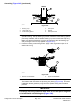
6.Slidespacerringandinnerbearingspacerintospindlehousing,theninstall
upperbearingconeandoilsealintotopofhousing.Note:Theupperseal
musthavethelipfacingin(down)(Figure348).Also,uppersealshouldbe
ushorupto1.5mm(0.060in)recessedintohousing.
7.Inspectthespindleshaftandshaftspacertomakesuretherearenoburrs
ornicksthatcouldpossiblydamagetheoilseals.Lubricatetheshaftand
spacerwithgrease.
8.Installspindleshaftspacerontoshaft.Placethinsleeveortapeonspindle
shaftsplinestopreventsealdamageduringshaftinstallation.
9.Carefullyslidespindleshaftwithspacerupthroughspindlehousing.The
bottomoilsealandspindlespacerttogetherwhenthespindleisfully
installed.
10.InstallO−ringtotopofspindleshaft.Fordrivespindle,positionhydraulic
motormounttotopofspindle.
11.Installpulley(hubdown),hardenedwasherandlocknuttospindleshaft.
Tightenlocknutfrom176to203N·m(130to150ft−lb).
IMPORTANT
Pneumaticgreasegunscanproduceairpocketswhenllinglarge
cavitiesandtherefore,arenotrecommendedtobeusedforproper
greasingofspindlehousings.
12.Attachahandpumpgreaseguntogreasettingonhousingandllhousing
cavitywithgrease.
13.Rotatespindleshafttomakesurethatitturnsfreely.
Groundsmaster
®
4000-D&4010-D
Page9–19
CuttingDecks:ServiceandRepairs
13202SLRevF