
Service Manual


2
1
g276897
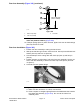
Figure303
1.Frontframebore2.Rearframebore
Note:Allowableclearancebetweenliftarmpivotshaft(item8)andfrontframe
bore(Figure303)isupto0.64mm(0.025in).Allowableclearancebetweenlift
armpivotshaftandrearframeboreisupto1.78mm(0.070in).
Removal(Figure302)
1.Parkmachineonalevelsurface,lowercuttingdecks,stopengine,apply
parkingbrakeandremovekeyfromtheignitionswitch.
2.Removesidedeckfromliftarm(seeSideCuttingDecks(page9–7)).
3.Removesidedeckreararmassemblyfrompivothub(seeSideDeckRear
ArmAssembly(page8–14)).
4.Removeliftcylinderpin(item28)thatsecuresliftcylindertoliftarm.
5.Driveoutslottedrollpin(item11)thatretainsliftarmpivotshaft.Discard
rollpin.
3” x 12” (3/8” to 1/2” thick) plate steel
9/16” hole
1/2” − 13 UNC bolt
Flat washer
1” to 1 1/8”
Use hammer to drive
pivot shaft from lift arm
g276898
Figure304
Chassis:ServiceandRepairs
Page8–12
Groundsmaster
®
4000-D&4010-D
13202SLRevF