
Service Manual


Testing(continued)
1
5
6
2
1
2
3
4
g276050
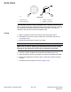
Figure243
1.Pin1(Violetwire)4.Pin4(Notused)
2.Pin2(Brownwire)
5.Motorpin
3.Pin3(Orangewire)
6.Resistormodule
4.Useamultimetertocheckthattheresistancevaluesoftheresistormodule
asbelow(Figure243).
TestPoint1TestPoint2ExpectedReading
MotorPinPin1Lessthan9ohms
MotorPinPin2Lessthan6ohms
MotorPinPin3Lessthan3ohms
5.Replacetheresistormoduleifitfailsthetest.
6.Iftheresistormoduletestingiscorrectandacircuitproblemstillexists,check
thewireharness;refertoElectricalSchematicsandWireHarnessDrawings
inAppendixA(pageA–1).
7.Afteryoucompletethetesting,connectthewireharnessconnectorstothe
resistormoduleterminals(Figure243)andinstallthesunshade.
Groundsmaster
®
4000-D&4010-D
Page6–87
ElectricalSystem:ComponentTesting
13202SLRevF