
Service Manual


RearTractionManifoldService
(115 ft−lb)
156 N·m
(20 ft−lb)
27 N·m
(50 ft−lb)
67 N·m
1
2
4
3
5
6
7
(25 ft−lb)
34 N·m
(25 ft−lb)
34 N·m
g275437
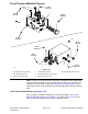
Figure113
1.Reartractionmanifoldbody4.#4zeroleakplugwithO−ring7.Orice(0.050)(portOR1)
2.Reliefvalve(portRV)5.#6zeroleakplugwithO−ring
3.Pressurereducingvalve(portPR)6.Checkvalve(portCV)
Note:Theportsonthereartractionmanifoldaremarkedforeasyidentication
ofcomponents.Example:P2isapistonpumpconnectionportandRVisthe
locationforthereliefvalve(seeAHydraulicSchematic(pageA–5)toidentifythe
functionofthehydrauliclinesandcartridgevalvesateachport).
Note:Thereartractionmanifoldusesseveralzeroleakplugs.Theseplugshave
ataperedsealingsurfaceontheplugheadthatisdesignedtoresistvibration
inducedplugloosening.ThezeroleakplugsalsohaveanO−ringasasecondary
seal.Ifzeroleakplugremovalisnecessary,lightlyraptheplugheadusinga
punchandhammerbeforeusinganallenwrenchtoremovetheplug:theimpact
willallowplugremovalwithlesschanceofdamagetothesocketheadoftheplug.
Forreartractionmanifoldcartridgevalveserviceprocedures,seeControl
ManifoldCartridgeValveService(page5–131).RefertoFigure113forrear
tractionmanifoldcartridgevalveandpluginstallationtorque.
IMPORTANT
Aowcontrolorice(item7)islocatedbeneaththehydraulictting
inreartractionmanifoldportT/OR1.Iftheoriceisremovedfrom
thismanifoldport,makesuretolabelitspositionforassembly
purposes.Wheninstallingtheoriceinthemanifold,makesurethat
theoriceisproperlytightenedintheport.
HydraulicSystem:ServiceandRepairs
Page5–122
Groundsmaster
®
4000-D&4010-D
13202SLRevF