
Service Manual


RearTractionManifold
FRONT
RIGHT
2
3
6
8
9
10
11
13
1
5
7
12
14
15
16
17
18
4
g275436
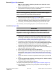
Figure112
1.Frontframe7.90ºhydraulictting13.O−ring
2.PTOmanifold(centerdeck)8.O−ring14.O−ring
3.Fronttractionmanifold9.45ºhydraulictting15.45ºhydraulictting
4.Reartractionmanifold10.O−ring16.O−ring
5.Capscrew(2used)11.O−ring17.O−ring
6.Flangenut(2used)12.Straighttting18.O−ring
Note:Theportsonthereartractionmanifoldaremarkedforeasyidentication
ofcomponents.Example:P2isapistonpumpconnectionportandRVisthe
locationforthereliefvalve(seeAHydraulicSchematic(pageA–5)toidentifythe
functionofthehydrauliclinesandcartridgevalvesateachport).
Removal(Figure112)
1.ReadtheGeneralPrecautionsforRemovingandInstallingHydraulicSystem
Components(page5–83).
2.Topreventcontaminationofhydraulicsystemduringmanifoldremoval,
thoroughlycleanexteriorofmanifoldandttings.
3.Disconnecthydrauliclinesfrommanifoldandputcapsorplugsonopen
hydrauliclinesandttings.Labeldisconnectedhydrauliclinesforproper
installation.
4.RemovehydraulicmanifoldfromtheframeusingFigure112asaguide.
5.Ifhydraulicttingsaretoberemovedfrommanifold,markttingorientationto
allowcorrectassembly.RemovettingsfrommanifoldanddiscardO−rings.
HydraulicSystem:ServiceandRepairs
Page5–120
Groundsmaster
®
4000-D&4010-D
13202SLRevF