
Service Manual


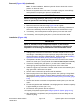


Removal(Figure109)(continued)
IMPORTANT
Beforelooseningfastenersthatsecurewheelmotor,supportmotor
topreventitfromfallingduringremoval.
5.RemovewheelmotorusingFigure109asaguide.
6.Ifhydraulicttingsaretoberemovedfromwheelmotor,marktting
orientationtoallowcorrectassembly.Removettingsfrommotoranddiscard
O−rings.
Installation(Figure109)
IMPORTANT
RefertoTractionCircuitComponentFailureintheGeneral
Informationsectionofthischapterforinformationregardingthe
importanceofremovingcontaminationfromthetractioncircuit.
1.Ifttingswereremovedfrommotor,lubricateandplacenewO−ringsonto
ttings.Installttingsintoportopeningsusingmarksmadeduringthe
removalprocesstoproperlyorientatettings.Tightenttings(seeInstalling
HydraulicHosesandTubes(O-RingFaceSeal)(page5–8)).
2.InstallnewO−ring(item8)ontomotor.
3.Alignsplinesonmotorshaftandsplinedbrakeshaft.Slidemotorintobrake
assembly.
4.Securemotortobrakeassemblywithcapscrewsandatwashers.
5.Removeplugsfromwheelmotorttingsandhydrauliclineopenings.Using
labelsplacedduringmotorremoval,correctlyattachhydraulichosesand
tubestowheelmotorttings(seeInstallingHydraulicHosesandTubes
(O-RingFaceSeal)(page5–8)).
6.Fillreservoirwithhydraulicuidasrequired.
7.Properlyllhydraulicsystem(seeChargeHydraulicSystem(page5–91)).
Groundsmaster
®
4000-D&4010-D
Page5–117
HydraulicSystem:ServiceandRepairs
13202SLRevF