
Service Manual


Installation(Figure101andFigure102)(continued)
2.Carefullyraisepistonpumpintothemachine,alignpumpinputshafttospring
coupleronengineandpositionittotheengineywheelplate.Supportpump
topreventitfromproducinganysideloadintocouplerandalsotoalignpilot
diameterofpumptoywheelplatebore.
3.Whilemaintainingpumpalignmentwithspringcouplerandywheelplate,
installtwo(2)capscrewsandwasherstosecurepistonpumptoengine.
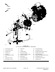
IMPORTANT
Acasedrainexistsinthepiston(traction)pumpandasuctionport
isneartheinputshaftofthegearpump(Figure104).Beforethegear
pumpisinstalledtothepistonpump,makesurethatplugsplacedin
eitheroftheseportsareremoved.Failuretoremoveplugswillcause
excessivepressureinthepistonpumpanddamageseals.Also,
beforesecuringgearpumptopistonpump,llpistonpumphousing
withcleanhydraulicoilthroughcasedrainhole.
4.Removeplugsthatwereplacedinpistonpumpcasedrainandgearpump
suctionport.Fillpistonpumphousingwithnewhydraulicoilthroughcase
drainhole.
5.Installgearpumptopistonpump(seeGearPump(page5–97)).
6.Usinglabelsplacedduringpumpremoval,connectwireharnessconnectors
tothetwo(2)solenoidcoilsonleftsideofpistonpump.
2
3
1
g275430
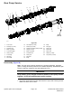
Figure105
1.Piston(traction)pump
3.Pistonpumpcasedrain
2.Gearpump
7.Fillpiston(traction)pumphousingwithnewhydraulicoilthroughthecase
drain(90ºbarbedtting)atthetopofthepump(Figure105).Thiswill
ensurethatinternalpumpcomponentshaveadequatelubricationduring
initialoperation.
8.Removeplugsandcapsfromdisconnectedhydrauliclinesandttingsof
thepumpassembly.Installhydrauliclinestocorrectlocationongearand
pistonpumps(seeInstallingHydraulicHosesandTubes(O-RingFaceSeal)
(page5–8)).
9.Lowermachinetoground.
10.Installnewhydrauliclterandllhydraulicreservoirwithcorrectoil.
Groundsmaster
®
4000-D&4010-D
Page5–109
HydraulicSystem:ServiceandRepairs
13202SLRevF