
Service Manual

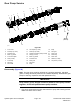


Assembly(Figure98)
2
3
1
4
g275426
Figure100
1.LHandRHPTOpumpsection3.Coolingfan,lift/lowerandchargepump
section
2.FrontPTOpumpsection4.Steering,chargeandcoolingfanpump
section
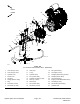
1.Applycleanhydraulicoiltoallpartsbeforeassembling.
Note:Pressuresealsandback−upgasketstingroovesmachinedinto
thrustplates.Bodysealstingroovesmachinedinbodyfaces.
2.Assemblepumpsectionsstartingatfrontcoverend.Applygreaseor
petroleumjellytonewsectionsealstoholdtheminpositionduringgear
pumpassembly.
3.Afterpumphasbeenassembled,tightencapscrewsbyhand.Rotatethe
driveshafttocheckforbinding.Protecttheshaftifusingapliers.
4.Tightenthefour(4)capscrewsevenlyinacrossingpatterntoatorqueof45
N·m(33ft−lb).
HydraulicSystem:ServiceandRepairs
Page5–104
Groundsmaster
®
4000-D&4010-D
13202SLRevF