
Operator's Manual


g011490
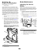
Figure83
1.Height-of-cutchain
2.U-bolt
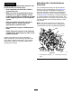
AdjustingtheSideCuttingUnit
Pitch
ServiceInterval:Every800hours
1.Removethetensioningcapfromthespindle
shaftandslidethespindleoutofthecasterarm
(Figure84).
Note:Positiontheshims,asrequired,toraise
orlowerthecasterwheeluntilthecuttingunit
hasthecorrectpitch.
g008866
Figure84
1.Tensioningcap4.Axle-mountingholes
2.Spacers5.Casterwheel
3.Shims
2.Installthetensioningcap.
ServicingtheCaster-Arm
Bushings
RemovingtheBushings
Thecasterarmshavebushingspressedintothe
topandbottomofthetubeandaftermanyhoursof
operation,thebushingsdevelopwear.Tocheckthe
bushings,movethecasterforkbackandforthand
fromsidetoside.Ifthecasterspindleislooseinside
thebushings,replacethebushings.
1.Raisethecuttingunitsothatthewheelsareoff
theoorandblockthecuttingunitsoitcannot
fall.
2.Removethetensioningcap,spacer(s),and
thrustwasherfromthetopofthecasterspindle.
3.Pullthecasterspindleoutofthemountingtube.
Note:Keepthethrustwasherandspacer(s)on
thebottomofthespindle.
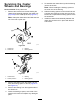
4.Insertapinpunchintothetoporbottomofthe
mountingtubeanddrivethebushingoutofthe
tube(Figure85).
g004737
Figure85
1.Caster-armtube
2.Bushings
5.Drivetheotherbushingoutofthetube.
6.Cleantheinsideofthetubestoremovedirt.
InstallingtheBushings
1.Applygreasetotheinsideandoutsideofthe
newbushings.
2.Usingahammerandatplate,drivethe
bushingsintothemountingtube.
3.Inspectthecasterspindleforwearandreplace
itifitisdamaged.
4.Pushthecasterspindlethroughthebushings
andmountingtube.
5.Slidethethrustwasherandspacer(s)ontothe
spindleandinstallthetensioningcaponthe
casterspindletoretainallpartsinplace.
68