
Service Manual


ParkingBrakeSwitch
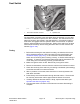
(34 to 42 in−lb)
3.9 to 4.7 N·m
2
3
6
1
5
4
g276005
Figure196
1.Locknut
4.Carriagebolt
2.Parkingbrakeswitch5.Parkingbrakerod
3.Switchplate6.Steeringtowercover
Theswitchusedfortheparkingbrakeisanormallyopenproximityswitchthatis
locatedunderthesteeringtowercover(Figure196).Theparkingbrakeswitch
isaninputfortheTECcontroller.Whentheparkingbrakeisnotapplied,atab
onthebrakerodispositionedneartheswitchsensezonewhichcausesthe
switchtoclose(continuity).Whentheparkingbrakeisapplied,thebrakerod
tabispositionedawayfromtheswitchallowingtheswitchtobeinitsnormal,
openposition(nocontinuity).
SwitchTesting
1.Beforedisconnectingtheparkingbrakeswitchfortesting,theswitchandits
circuitwiringshouldbetestedasaTECinputwiththeInfoCenterDisplay
(seeInfoCenterDisplay(page6–6)).IftheInfoCenterveriesthatthebrake
switchandcircuitwiringarefunctioningcorrectly,nofurtherswitchtestingis
necessary.If,however,theInfoCenterdeterminesthatthebrakeswitchand
circuitwiringarenotfunctioningcorrectly,proceedwithtest.
2.MakesureignitionswitchisOFF .Removekeyfromignitionswitch.
3.Removefrontsteeringtowercover(seeSteeringT ower(Formachinesserial
numberbelow:400000000)(page8–3)).
4.Locateparkingbrakeswitchandunplugwireharnessconnectorfromswitch.
5.Checkthecontinuityoftheswitchbyconnectingamultimeter(ohmssetting)
acrosstheconnectorterminals.
6.Whentheparkingbrakeisnotapplied(brakerodtabclosetobrakeswitch),
thereshouldbecontinuity(zeroresistance)betweentheswitchterminals.
7.Whentheparkingbrakeisapplied(brakerodtabawayfrombrakeswitch),
thereshouldbenocontinuity(inniteresistance)betweentheswitch
terminals.
ElectricalSystem:ComponentTesting
Page6–40
Groundsmaster
®
4000-D&4010-D
13202SLRevF