
Service Manual


Removal(Figure116)(continued)
2
3
6
8
9
10
11
14
1
5
7
12
4
2
2
2
13
g275441
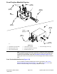
Figure117
1.Manifold8.Straighttting
2.Straighttting9.Barbed90ºtting
3.Straighttting
10.Hoseclamp
4.Straighttting
11.Hose
5.Oillter12.90ºtting
6.Straighttting
13.T estnipple
7.Straighttting14.Straighttting
6.Ifhydraulicttingsaretoberemovedfrommanifold,markttingorientation
toallowcorrectassembly(Figure117).Removettingsfrommanifoldand
discardO−rings.
Installation(Figure116)
1.Ifttingswereremovedfrommanifold,lubricateandplacenewO−ringsonto
ttings.Installttingsintomanifoldopeningsusingmarksmadeduringthe
removalprocesstoproperlyorientatettings.Tightenttings(seeInstalling
theHydraulicFittings(SAEStraightThreadO-RingFittings)(page5–10)).
2.InstallcombinationmanifoldtotheframeusingFigure116asaguide.
3.Removecapsandplugsfromttingsandhydrauliclines.Usinglabelsplaced
duringmanifoldremoval,properlyconnecthydrauliclinestomanifold(see
InstallingHydraulicHosesandTubes(O-RingFaceSeal)(page5–8)).
4.Usinglabelsmadeduringmanifoldremoval,connectwireharnessconnectors
tothesolenoidcoilsonthecombinationmanifold.
5.Makesurehydraulictankisfull.Addcorrectoilifnecessarybeforereturning
machinetoservice.
HydraulicSystem:ServiceandRepairs
Page5–128
Groundsmaster
®
4000-D&4010-D
13202SLRevF