
Service Manual


Installation(continued)
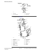
3.Slidethebevelgearcaseoverthebevelgearshaftandinstallthebevel
gearandcollar.Makesurethebevelgearshaftiscompletelyseatedinthe
upperandlowerbearings(Figure269).
4.Installtheknucklepin.Usemediumstrengththreadlockingcompoundand
tightentheknucklepinmountingscrewsfrom23to27N·m(17to20ft-lb).
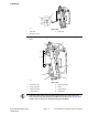
1
2
4
5
3
6
VERTICAL
ENDPLAY
(57 to 67 ft-lb)
77 to 91 N·m
g276516
Figure270
1.Axlecasesupport4.Dialindicator
2.Axlecase5.Knucklepin
3.Bevelgearcase
6.Supportshimlocation
5.Determinenecessaryquantityofsupportshims.
A.Lubricatetheaxlecasesupportbushingwithathincoatofgreaseand
slideaxlecasesupportontoknucklepin.
B.Positionsupportshimsthatwereremovedduringdisassemblybetween
axlecasesupportandaxlecase.Installmountingscrewsintoaxle
case.Slowlytightenscrewswhilefrequentlycheckingforclearance
(verticalendplay)betweenaxlecasesupportandknucklepin.Ifbinding
ofcomponentsisnotedbeforescrewsarefullytightened,addadditional
supportshims.T orquescrewsfrom77to91N·m(57to67ft−lb).
C.Usedialindicatortomeasureverticalendplayofaxlecase(Figure270).
AXLECASEASSEMBLYENDPLAY:0.02to0.20mm(0.001to0.008in)
D.Adjustendplaybyincreasingorreducingnumberofaxlecasesupport
shims.
Note:Axlecasesupportshimsareavailablein0.1mm(0.004in),0.2mm
(0.008in)and0.4mm(0.016in)thickness.
6.Aftercorrectsupportshimshavebeendetermined,removemountingscrews,
applyheavystrengththreadlockingcompoundtoscrewthreads,reinstall
screwsandtorquefrom77to91N·m(57to67ft−lb).
IMPORTANT
Correctengagementbetweenbevelgearsiscriticaltoaxle
performanceanddurability.
Axles,PlanetariesandBrakes:ServiceandRepairs
Page7–32
Groundsmaster
®
4100-D&4110-D
13203SLRevE