
Service Manual


ToroElectronicControllers(TEC)(continued)
IMPORTANT
Whentestingforwireharnesscontinuityattheconnectorforthe
TECcontroller,takecaretonotdamagetheconnectorpinswith
multimetertestleads.Ifconnectorpinsareenlargedordamaged
duringtesting,connectorrepairwillbenecessaryforproper
machineoperation.
ThemachineelectricalschematicandwireharnessdrawingsinAppendix
A(pageA–1)canbeusedtoidentifypossiblecircuitproblemsbetweenthe
controllersandtheinput/outputdevices(e.g.switchesandsolenoidcoils).
BecauseofthesolidstatecircuitrybuiltintotheTECcontrollers,thereisno
methodtotestacontrollerdirectly.Acontrollermaybedamagedifanattemptis
madetotestitwithanelectricaltestdevice(e.g.digitalmultimeterortestlight).
IfremovaloftheTECcontrollersisnecessary,labelthecontrollerstomake
suretheyareproperlyconnectedtothemachine.Thetwo(2)TECcontrollers
arevisuallyidenticalbuttheyhavedifferentsoftwareandthereforecannot
beinterchanged.Thepowermount(item5inFigure215)canbeseparated
fromtheoperatorplatformandcarefullyliftedfromtheplatformtoaccessthe
controllerfasteners.
Note:TheTECcontrollersusedontheGroundsmaster4100−Dand4110−D
arematchedforcorrectmachineoperation.Ifeitherofthesecomponentsare
replacedforanyreason,systemsoftwareneedstobereprogrammedbyyour
ToroDistributor.
IMPORTANT
BeforeperforminganyweldingonyourGroundsmaster,disconnect
bothpositiveandnegativebatterycablesfromthebattery,
disconnectthewireharnessconnectorfrombothoftheTEC
controllersanddisconnecttheterminalconnectorfromthe
alternator.Also,disconnectandremovetheengineECUfromthe
machinebeforewelding.Thesestepswillpreventdamagetothe
machineelectricalsystem.
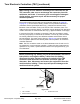
g321413
Figure219
1.TECcontroller3.Socketheadscrew
2.Machineharnessconnector
ElectricalSystem:ComponentTesting
Page6–64
Groundsmaster
®
4100-D&4110-D
13203SLRevE