
Operator's Manual


54
Replacing the Blade Drive
Belts
Position machine on level surface, lower cutting unit to
shop floor, engage parking brake, shut engine off and
remove key from ignition switch.
Front Cutting Unit
Note: To remove center section belt, wing spindle drive
belts must first be removed.
1. Remove deck covers. Lift each wing to release idler
pulley tension and slip belt off pulleys.
2. Loosen jam nut and relieve tension on springs with
tensioner bolt (Fig. 69).
1
2
4
5
6
7
8
10
10
9
11
12
13
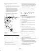
Figure 69
1. Slide plate
2. Motor mount
3. Drive motor
4. Drive pulley
5. Taper lock bushing
6. Compression spring
7. Spring holder
8. Slide bar
9. Adjusting screw (rear)
10. Adjusting screws (front)
11. Tensioner bolt
12. Height gauge
13. Center deck spindle
3. Locate and remove the adjusting screw and nut from the
tool box.
4. Thread the nut onto the adjusting screw and thread the
screw into the rear of the motor mount (Fig. 69).
5. Loosen the (4) capscrews securing the slide plate to the
motor mount (Fig. 69).
6. Remove the (4) flangehead capscrews and washers
securing the motor mount to the deck (Fig. 69).
Note: Do not loosen the adjusting screws.
7. Replace belt(s) as required. Install on pulleys as shown
in figure 70.
8. Position motor mount onto deck while routing belt
around drive pulley (Fig. 69). Be careful not to bend,
twist, kink or damage flexible hydraulic lines.
9. Loosely secure motor mount to deck with the (4)
flangehead capscrews and washers previously removed.
10. Check the drive pulley (Fig. 69) height as follows:
• Slide the height gauge (Fig. 69) under drive pulley (not
under taper lock bushing).
• Equally tighten or loosen (3) adjusting screws (Fig. 69)
until bottom of pulley rests flush on height gauge
(approximately 1–1/2”).
• Tighten the front adjusting screw nuts to lock the
adjustment. Remove the height gauge and store it in the
tool box.
• Tighten the (4) flangehead capscrews and washers
securing motor mount to deck.
• Remove the rear adjusting screw and nut and store them
in the tool box.
11. Tighten tensioner bolt until springs are compressed to
dimension shown in figure 67.
12. Tighten jam nut securing adjustment (Fig. 67).
13. Tighten (4) capscrews securing slide plate to motor
mount (Fig. 67).
1
2
3
4
Figure 70
1. Top and middle grooves
2. Bottom grooves
3. Top grooves
4. Top and middle grooves