
Service Manual


Groundsmaster 360Hydraulic System Page 4 − 68
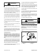
Wheel Motor Service
1. Cap screw (7)
2. End cover
3. Body seal (5)
4. Commutator ring
5. Commutator
6. Commutator ring
7. Manifold
8. Stator
9. Vane (7)
10. Rotor
11. Wear plate
12. Drive link
13. Thrust bearing
14. Coupling shaft
15. Shaft seal
16. Back−up washer
17. Back−up ring
18. Housing
19. Dirt and water seal
Figure 51
(61 to 75 N−m)
45 to 55 ft−lb
4
3
1
2
9
10
11
8
5
6
7
12
3
3
3
3
13
14
15
16
17
18
19
NOTE: The wheel motors used on the Groundsmaster
360 have the same basic construction. The left wheel
motor(s) has a yellow sticker on the port side of the sta-
tor. The right wheel motor(s) has a reverse timed man-
ifold.
IMPORTANT: DO NOT interchange wheel motors on
machine (i.e. do not put RH motor on left side of ma-
chine). If necessary, use parts catalog and part num-
ber on wheel motor to identify RH and LH motors.
NOTE: For wheel motor repair procedures, see the
Parker Torqmotor
TM
Service Procedure (TC, TB, TE, TJ,
TF, TG, TH and TL Series) at the end of this chapter.
IMPORTANT: If a wheel motor failure occurred, refer
to Traction Circuit (Closed Loop) Component Fail-
ure in the General Information section for informa-
tion regarding the importance of removing
contamination from the traction circuit.