
Service Manual


Rev. A
Groundsmaster 360 Page 6 − 23 Chassis
Removal (Fig. 25)
1. Park machine on a level surface, lower cutting deck,
stop engine and remove key from the ignition switch.
2. Chock wheels to prevent machine from shifting.
3. Loosen, but do not remove, wheel lug nuts on front
wheel at steering fork to be removed.
4. Jack up machine and remove front wheel assembly
(see Wheel Removal in this section). Make sure to sup-
port machine with jack stands.
5. Remove cotter pin and slotted hex nut that secure tie
rod end to the steering fork (Fig. 27). Separate tie rod
end from the steering fork.
6. If steering fork assembly includes a wheel motor:
A. Remove two (2) cap screws (item 34) that secure
bulkhead bracket (item 23) to steering fork.
B. Remove four (4) cap screws that secure wheel
motor to steering fork. Slide wheel motor assembly
(with wheel hub and hydraulic lines attached) from
steering fork. Carefully, position wheel motor away
from steering fork taking care to not damage hydrau-
lic lines.
7. Support steering fork to prevent it from falling.
CAUTION
Support steering fork assembly when removing
it to prevent it from falling and causing personal
injury. Assembly weighs approximately 50
pounds (23 kg).
8. Remove the flange head screw (item 21), spindle
cap (item 20) and retaining ring (item 19) that secure the
steering fork shaft into the axle tube. Slide the steering
fork out of the axle tube. Locate and retrieve thrust
washers (items 7 and 11) from steering fork spindle.
9. Thoroughly clean the steering fork spindle. Inspect
the shaft for wear and replace steering fork spindle if
shaft is worn or damaged (Fig. 28). If spindle was re-
moved from steering fork, torque cap screws from 94 to
116 ft−lb (128 to 157 N−m) during assembly.
10.Clean and inspect flange bushings in axle. If bush-
ings are worn or damaged, replace bushings (see Steer-
ing Assembly Bushing Service in this section).
NOTE: On 2WD machines, if spindle or wheel hub re-
quires removal or service, see Front Spindle Assembly
(2WD Machines) in this section.
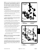
1. Front axle
2. Spindle (2WD machines)
3. Steering fork assembly
4. Cap screw (4)
5. Flange head screw
6. Spindle cap
7. Retaining ring
8. Thrust washer
9. Thrust washer
Figure 26
2
3
6
8
9
1
5
7
4
2WD FRONT AXLE
SHOWN
FRONT
RIGHT
Loctite #271
94 to 116 ft−lb
(128 to 157 N−m)
1. Front steering fork
2. Slotted hex nut
3. Cotter pin
4. Tie rod
Figure 27
4
3
2
1
35 to 40 ft−lb
(48 to 54 N−m)
RH FRONT FORK
SHOWN
Chassis