
Service Manual


Groundsmaster 360Page 5 − 14Electrical System
(Rev. A)
Standard Control Module Logic Chart (2WD Machines)
Each line of the following chart identifies the necessary
component position (INPUTS) in order for the Standard
Control Module (SCM) to energize the appropriate
OUTPUTS for machine operation.
Example: To start the engine with an operator in the
seat, when the ignition key is in START, the traction con-
trol pedal is in the neutral position and the parking brake
is not applied, engine components and the engine start-
er will be energized.
INPUTS
MACHINE FUNCTION
Engine Start (Operator in Seat)
Engine Run (Operator in Seat)
High Temperature Warning
Mow
High Temperature Shutdown
Power
Start
Neutral
Parking Brake Off
PTO Switch
In Seat
High Temperature Warning
OUTPUTS
PTO
Engine Run
LED ON − Circuit closed to ground
LED ON − Circuit is energized
LED OFF − Circuit is open to ground or circuit is de−energized
KEY TO CHART
Engine Run (No Operator in Seat)
High Temperature Shutdown
Engine Start
−
+
Backlap
Circuit is not involved with this machine function (LED OFF)
+−
−
−
−
−
−
−
−
−
− −
−
−
−
+
NA
NA
NA
NA
NA
NA
+
+
−
−
−
−
−
−
−
NA Backlap Input is not used on the Groundsmaster 360
Engine Start (No Operator in Seat)
− −
−
NA
−+ −
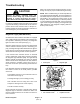
IMPORTANT: During machine operation, if the PTO
shuts down and the console temperature warning
light is illuminated, avoid shutting off the engine.
Under this condition, the operator should push the
PTO knob down, slowly drive to a safe flat area,
move the throttle lever to the SLOW position, re-
lease the traction control pedal to the neutral posi-
tion and engage the parking brake. The engine
should be allowed to low idle speed for several min-
utes while it cools to a safe level. Then, the cooling
system should be checked before returning the ma-
chine to service.