
Service Manual


Groundsmaster 360 Operator CabPage 8.1 − 15
(Rev. A)
Removal (Fig. 8)
1. Park machine on a level surface, lower lower cutting
deck or implement and stop engine. Remove key from
the ignition switch.
2. To access A/C condenser assembly, remove roof
panel from top of cab (see Roof Assembly in this sec-
tion).
3. Remove condenser fan assembly from machine
(see A/C Condenser Fan Assembly in this section).
4. Read the General Precautions for Removing and
Installing Air Conditioning System Components at the
beginning of the Service and Repairs section of this
chapter.
CAUTION
The air conditioning system is under high pres-
sure. Do not loosen any system fitting or compo-
nent until after the system has been completely
discharged by a certified A/C service technician
.
5. Have refrigerant evacuated from air conditioning
system by a certified A/C service technician.
6. Label and disconnect hoses from condenser core.
Immediately cap hoses and fittings to prevent moisture
and contaminants from entering the system.
7. Remove four (4) flange nuts that secure A/C con-
denser assembly to cab frame.
8. Carefully raise condenser assembly from headliner
and remove from machine.
9. Inspect seals (items 7 and 8 in Fig. 8) on top of cab
frame for wear or damage and replace if needed.
10.If necessary, disassemble condenser assembly us-
ing Figure 9 as a guide. Inspect seals on top of con-
denser assembly walls (items 8 and 9 in Fig. 9) for wear
or damage and replace if needed.
Installation (Fig. 8)
1. If condenser assembly was disassembled:
A. To properly seal condenser core, apply RTV
sealant to all mating surfaces of walls, lower legs and
condenser core before assembly.
B. Assemble all condenser assembly components
using Figure 9 as a guide. Make sure that strip and
edge seals are in good condition after assembly.
2. Carefully lower the A/C condenser assembly
through headliner and onto cab frame.
3. Secure A/C condenser assembly to cab frame with
four (4) flange nuts.
4. Remove caps that were placed on hoses and fittings
during the removal process. Using labels placed during
removal, properly secure hoses to condenser core.
While holding condenser fittings with a second wrench,
torque hose swivels from 10 to 15 ft−lb (14 to 20 N−m).
5. Secure condenser fan assembly to machine (see
A/C Condenser Fan Assembly in this section).
6. Make sure that all machine air conditioning compo-
nents are installed and secure.
7. Have a certified air conditioning service technician
evacuate the air conditioning system completely, prop-
erly recharge the system with R134a refrigerant and
then leak test the system. A/C system capacity is 3.44
pounds of R134a refrigerant.
8. When all service in cab headliner is completed, se-
cure roof panel to top of cab (see Roof Assembly in this
section).
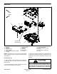
1. Condenser core
2. Lower leg (2)
3. Hex nut (6)
4. Front wall
5. Back wall
6. Right side wall
7. Left side wall
8. Strip seal (2)
9. Edge seal (2)
10. Screw (12)
11. Clip (16)
Figure 9
2
3
6
8
9
10
11
1
5
7
4
9
8
2
Operator
Cab