
Service Manual


Groundsmaster 360Hydraulic System Page 4 − 72
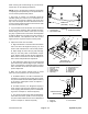
5. For correct operation of Automatic Speed Control
(ASC), adjust the ASC control arm as follows (Fig. 59):
NOTE: Before adjusting the ASC control arm, make
sure that traction pedal stop is correctly adjusted.
A. With the rear wheels in the straight forward posi-
tion (not turned), fully depress and hold the traction
pedal in the full forward direction.
B. Check that the clevis spring pin that secures the
ASC control arm to the speed control shaft is just
contacting the rear of the slot in the speed control
shaft.
C. If necessary, loosen jam nuts on ASC control arm
and adjust control arm length until clevis spring pin
just contacts the rear of the control shaft slot. Make
sure that linkage yoke and ball joint on ASC control
arm are at right angles (90
o
). Tighten control arm jam
nuts after adjustment.
D. Make sure that ASC control arm does not bind
through complete range of operation.
6. After adjustments have been made and all traction
linkage fasteners are tightened, make sure that no bind-
ing exists as the traction pedal is depressed. The trac-
tion pedal should freely return to the neutral position
after it is released from either forward or reverse. Also,
make sure that the traction rod does not contact any-
thing through both forward and reverse directions.
1. Transmission assembly
2. Control arm
3. Alignment pin
Figure 57
1
3
2
1. Ball joint (LH threads)
2. Jam nut (LH threads)
3. Control arm
4. Jam nut
5. Rod end
Figure 58
2
3
1
5
4
1. ASC control arm
2. Clevis spring pin
3. Speed control slot
4. Linkage yoke
5. Ball joint
Figure 59
1
3
2
5
4