
Service Manual


ELECTRICAL
8 - 14 Mid-Size Walk Behind Service Manual
Delay Module (2000 and Earlier)
Purpose
The delay module is part of the electric clutch system.
The operator must squeeze a bail to maintain power to
the electric clutch. The module allows a slight delay
between release of the bail and clutch disengagement.
If the module was not there, the operator would need to
restart the clutch even if their hand slipped off
momentarily. The module allows about a second
delay.
Location
The module is located under the control panel on the
upper handle.
Testing
There is no process to test the module. In fact, an
ohmmeter connected to the wrong terminals can cause
internal damage. Disconnect the module from the
circuit before using an ohmmeter or continuity light.
Test the wires and switches, if they are good and the
problem persists, replace the module.
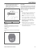
Figure 238
0821-03
Delay Module 104-8141
(T-Bar Floating Deck Electric Clutch
2001 & Up)
Purpose
The delay module monitors the status of the interlock
system and prevents engagement of the electric clutch
if it detects an unsafe condition.
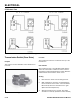
How It Works
DC voltage is connected to the common terminal of a
relay located on the module. Pressing the PTO
momentary switch energizes the relay which then
supplies power to the electric clutch. The relay
remains energized as long as the bail switch is closed.
If the operator releases the bail, the relay will de-
energize after a .5 (half) second delay and remove
power from the electric clutch.
P2 is the outlet for an hourmeter for non-electric start
mowers. Some modules with electric start may not
have P2 terminal.