
Service Manual


CRANKSHAFT AND CAMSHAFT
9-4
NOTE: Radial oil-grooves of
the
link rods must
be
toward the outside of
the
crankwebs.
Install
balance
weight to crankshaft with oil hole
(7)
facing flywheel side.
Bearing Surface Dia. (MIN)
If bearing surface diameter
is
less
than MIN,
replace camshaft.
Lobe
Height (MIN)
If lobe height
is
less
than MIN for either lobe,
replace camshaft.
CRANKSHAFT AND CAMSHAFT
INSTALLATION
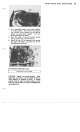
1.
Assemble crankshaft, link rods, collares, gear
and balance weight
as
illustrated below.
16 17 18
I
7
8
1.
Crankshaft
2.
Crankcase
3.
Oil
seal
10.
Washer
11.
Support shaft
12.
Stud
4.
Ball bearing
13.
Bushing
5.
Collar
14.
Wrist pin
6.
Balance weight
15.
Link rod
7.
Oi
hole
16.
Crank gear
8.
O-ring
9.
Nut
17.
Collar
18.
Bushing
2.
Cover key way on flywheel end of crankshaft
with
a
tape to prevent
seal
damage when
installing crankshaft.
3.
Put
a
light film of oil on crankshaft bearing
surfaces.
4.
Pack preferably high temperature grease
into oil
seals.
5.
Put crankpin
at
bottom dead center of engine.
Install crankshaft carefully.
6.
Align center hole of balance weight and
support shaft hole in crankcase.
7.
Install support shaft, O-ring and nuts.
8.
Install con-rod and piston assembly.
9.
Install tappets in their respective guides from
(See
Section
8)
which they were removed.
NOTE: Push tappets
all
the way in to
valve
guides
to prevent damage to tappets when installing
camshaft.
Install governor shaft and snap pin by properly
positioning
the
shaft,
pin and projection-stopper
as
illustrated.
1.
Case
cover mounting face
2.
Crankcase
3.
Snap pin
4.
Governor shaft
5.
Stopper (projection)
6.
Governor shaft in crankcase