
Service Manual


5-3
GOVERNOR
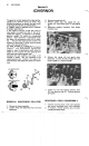
THROTTLE CABLE INSTALLATION
AND ADJUSTMENT
Make sure that the throttle lever and cable on
equipment have the speed control linkages with
engine.
1.
2.
3.
4.
Leave
cable clamp bolt (A) loose.
Align hole
(B)
of speed control lever
(C)
with
hole (D) of control plate
(E)
moving the lever;
insert
a
(6
mm)
0.24
in. dia. pin (or
a
6
mm
bolt) through the two holes.
Pull up outer housing
(F)
of throttle cable
until the inner cable
(G)
has almost no slack,
and tighten the cable clamp bolt.
Remove the
6
mm dia. pin.
Be
sure that carb. choke
valve
(H)
is
closed
completely when throttle lever on equipment
is
moved to "CHOKE" position. If not, per-
form "CHOKE ADJUSTMENT,, described
below.
CHOKE ADJUSTMENT
1.
Align hole (B) of speed control lever
(C)
with
hole (D) of control plate
(E)
moving the lever;
insert
a
6
mm
(0.24
in.) dia. pin (or
a
6
mm
dia. bolt) through the two holes.
2.
Turn in choke setting screw (K) until
its
end
just begins to touch the tongue of lever
(L).
3.
Remove the
6
mm dia. pin
or
bolt.
MAXIMUM SPEED ADJUSTMENT
Start
engine and allow
it
warm.
1.
Align hole
(B)
of speed control lever
(C)
with hole (D) of control plate
(E)
by moving
the lever; insert
a
(6
mm)
0.24
in. dia. pin
(or
a
6
mm bolt) through the two holes.
2.
Leave two control-plate-tightening-bolts
(I)
loose.
3.
Use
a
tachometer and slide control plate
(E)
left
or right to obtain specified
3,350
rpm.
Be
sure that the carb. choke
valve
is
fully
opened during adjustment.
4.
Tighten two bolts
(I)
securely in
a
manner to
avoid changing the specified speed.
5.
Adjust choke per procedure previously men-
tioned.
6.
Remove the
6
mm dia. pin or bolt.
7.
Stop engine.
IDLE SPEED ADJUSTMENT
Before the following procedure, carb. adjustment
must be performed.
(See
CARBURETOR ADJUSTMENT)
Start engine and allow
it
warm.
1.
Move throttle lever on equipment to farest
IDLE position and leave
it
there.
2.
Turning throttle stop screw (J) in or out to
obtain specified idling
1,350
to
1,450
rpm.
3.
Stop engine.