
Operator's Manual


12
Setup
Note: Determine the left and right sides of the machine from the normal operating position.
Loose Parts
Note: Use the chart below to verify all parts have been shipped.
DESCRIPTION
QTY. USE
Caster assemblies
Bolt, 3/8 x 3/4 inch
Flange nut, 3/8 inch
2
8
8
Installing the front casters
Upper handle
Flanged bolt, 3/8 x 1 inch
Flanged nut, 3/8 inch
Wire tie
1
4
4
2
Installing the upper handle and wire harness
Clevis pin
Washer
Hairpin cotter
2
2
2
Installing the control rods
Fuel tank
Bolt, 5/16 x 3/4 inch
Lock washer, 5/16 inch
Locknut
Washer, 5/16 inch
Stud
Spring
1
2
2
2
4
2
2
Installing the fuel tank
Operator’s Manual
Engine Operator’s Manual
Parts Catalog
Video
1
1
1
1
Review before operating machine
Registration card 1 Fill out and return to Toro
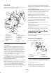
Installing the Front Casters
1. Align the casters with the holes on the top and front of
the mower, and insert 8 bolts (3/8 x 3/4 inch) through
the mower. Secure the casters with 8 flange nuts
(3/8 inch) below the mower (Fig. 2).