
Operator's Manual


16
5. Torque the nut to 35 ft–lb (47 NSm).
6
1
m–3772
5
2
3
4
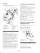
Figure 11
1. Shift lever
2. Control panel
3. Rubber seal washer
4. Square hole washer
5. Spring washer
6. Locknut 3/8
Adjusting the Shift Lever Plate
1. Shift lever to second gear and check alignment of lever
in slot of shifter lever plate. The clearance between top
and bottom of the shift lever should be equal (Fig. 12).
2. If clearance is not correct, remove lever and bend it
slightly to adjust (Fig. 12).
Note: Do not bend lever while attached to transmission
shaft or damage may occur.
3. Shift lever to neutral and check alignment of lever in
slot of shifter lever plate. The clearance on the sides of
shift lever should be equal (Fig. 12).
4. If clearance is not correct, loosen shift lever plate and
adjust it side–to–side. Tighten the shift lever plate.
4
Rear View
1
4
3
2
2
m–7454
Figure 12
1. Shift lever, 2nd gear
2. Shift lever plate
3. Shift lever, neutral
4. Equal distance
Mounting the Fuel Tank
1. Align fuel tank with the top of the rear frame (Fig. 13).
2. Secure the right side of the fuel tank to the rear frame
with 2 bolts (5/16 x 7/8 inch), lock washers (5/16 inch)
and washers (5/16 inch) (Fig. 13).
3. Secure the left side of the fuel tank to the rear frame
with 2 studs, washers (5/16 inch), springs and locknuts
(5/16 inch) (Fig. 13).
Note: Tighten left side of the fuel tank until it is completely
tight and then unscrew locknut one full turn. This will
allow the spring to work.
m–3771
1
2
3
5
4
6
3
Figure 13
1. Bolt, 5/16 x 7/8 inch
2. Lock washer, 5/16 inch
3. Washer, 5/16 inch
4. Stud
5. Spring
6. Locknut
4. Slide the hose clamp onto the fuel line (Fig. 14).