
Operator's Manual


22
Adjusting the Wheel Drive
Tension
You may need to increase the wheel drive belt tension
under certain operating conditions, such as mowing over
hilly terrain or while pulling a sulky.
1. Stop the engine and wait for all moving parts to stop.
2. Disconnect the wire from the spark plug.
3. Disengage the neutral/parking brake locks, and release
the drive levers to reduce the spring force.
4. Remove the drive spring from the adjustment bolt
(Fig. 16).
m–5372
1
2
3
4
5
6
Figure 16
1. Position A
2. Position B
3. Position C
4. Drive spring
5. Adjustment bolt ( In
position A)
6. Drive pulley shield
5. Remove the locknut that secures the adjustment bolt to
the drive pulley shield (Fig. 16).
6. Locate bolt assembly in the desired tension position as
follows:
• Position A for normal conditions
• Position B for more severe conditions
• Position C for the most severe conditions
Note: The wheel drive tension is lowest when the bolt
assembly is in Position A. The tension increases in
Positions B and C (Fig. 16).
7. Install the adjustment bolt and the drive spring.
8. Repeat steps 4 through 7 for the opposite side.
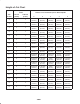
Adjusting the Height-of-Cut
This machine has a 1 to 4-1/4 inch (26 to 108 mm) range
for the height-of-cut. This can be achieved by adjusting
blade spacers, rear axle height, and front caster spacers.
Use the Height-of-Cut Chart on page 24 to select the
combination required.
Adjusting the Blade Height
Adjust the blades by using the 4 spacers (1/4 inch) on the
blade spindle bolts. This allows a range, in 1/4 inch (6 mm)
increments, of cutting height in any axle position. Use the
same number of blade spacers on all blades to achieve a
level cut (2 above and 2 below, 1 above and 3 below, etc.).
1. Disengage the blade control (PTO) lever and set the
parking brakes.
2. Stop the engine and wait for all moving parts to stop
before leaving the operating position.
3. Hold the blade bolt and remove the nut (Fig. 17).
m–3779
1
4
3
2
4
6
5
Figure 17
1. Blade
2. Blade bolt
3. Cone washer
4. Spacer
5. Thin washer
6. Nut
4. Slide the bolt down through the spindle, and change the
spacers as needed (Fig. 17).
5. Insert a bolt, add extra spacer(s), and secure them with a
thin washer and a nut (Fig. 17).
6. Torque the blade bolt to 75–80 ft-lb (101–108 Nm).
Adjusting the Axle Height
You can obtain the desired height-of-cut range by adjusting
the rear axle and placing the caster spacers above or below
the caster arm (refer to the Height-of-Cut Chart, page ).
1. Disengage the blade control (PTO) lever and set the
parking brakes.